
Step 1. Connect the Switch to PuTTY
To start configuration, you want to connect the switch console to PuTTY. You can do this by doing the following:
- Connect the switch to PuTTY with a 9-pin serial cable.
- Now open PuTTY and the PuTTY Configuration window will display. Go to the Connection type settings and check the Serial option (shown below).
- Go to the Category list section on the left-hand side and select the Serial option.
- When the options controlling local serial lines page displays enter the COM port your network is connected to in the Serial line to connect to box e.g. COM1.
- Next, enter the digital transmission speed of your switch model. For 300 and 500 Series Managed Switches, this is 115200.
- Go to the Data bits field and enter 8.
- Now go to the Stops bits field and enter 1.
- Click on the Parity drop-down menu and select the None option.
- Go to the Flow Control drop-down menu and select the None option.
Save Your Settings and Start the PuTTY CLI
To save your PuTTY settings for your next session do the following:
- Click on the Session option from the Category list on the left-hand side of the page.
- Go to the Saved Session field and enter a name for your settings e.g. Comparitech.
- Click the Save button to store the settings.
- Press the Open button at the bottom of the page to launch the CLI.
The following message will display in the command prompt:
Switch>
How do I configure a trunk port on a Cisco 2960 switch?
To configure a trunk port on a Cisco 2960 switch:
- Enter configuration mode:
configure terminal
- Specify the port to use:
interface <interface-id>
- Configure the port as a Layer 2 trunk:
switchport mode {dynamic {auto | desirable} | trunk}
These options mean:
- dynamic auto – The Default. Creates a trunk link if the neighboring interface is set to trunk or desirable mode.
- dynamic desirable – Creates a trunk link if the neighboring interface is set to trunk, desirable, or auto mode.
- trunk – Sets the interface in permanent trunking mode.
- Specify a default VLAN to use for back up. This is optional:
switchport access vlan <vlan-id>
- Specify the native VLAN:
switchport trunk native vlan <vlan-id>
- Exit the config mode:
Overview of Router Modes
The first step in configuring a router is to be located at privileged mode. Remember, exact modes have two sublevels: user and privileged. You go from user to privilege using the enable command and then from there you can only do monitoring and maintenance commands. If you want to configure, you have to go into global configuration mode at least, and you can accomplish that by typing configure terminal. That changes you to a different mode and the commands that you will have available are going to be different.
While in global configuration mode, anything you configure in that particular mode will affect the router as a whole typically, for example, the router’s host name and passwords and banners. If you want to configure specific components, then you would have to go into that components configuration mode from global configuration.
Interface configuration mode requires a command from global config and then the prompt changes to tell you that you are in a different configuration mode. This is similar for sub-interfaces, controllers, access lines and routing protocols. If you want to navigate back and forth between modes, exit takes you one mode back and Ctrl+Z takes you all the way back to privileged EXEC mode with no regards to your location. If you want to navigate between second level configuration modes, then you can do so without having to go back to global configuration mode.
How do I set a static IP on a Cisco switch?
A problem with the GUI interface of Cisco switches makes it impossible to assign a static IP address to an interface. Follow these steps for a workaround:
- Create a text file on your PC. It doesn’t matter where you save it or what you call it, but make sure you remember where it is. Substitute real values for the tokens shown in angle brackets (<>) below. The text in the file should be:
Config t
Interface <VLAN ID>
No ip address DHCP
Y
No ip address <old IP address>
IP address <new IP address> <subnet mask>
Exit
IP default-gateway <gateway IP address>
- Access the admin menu of the switch for Switch Management.
- In the menu, click on Administration, then File Management, and then select File Operations.
- In the File Operations screen, set the following:
- Operation Type: Update File
- Destination File Type: Running Configuration
- Copy Method: HTTP/HTTPS
- File Name: (Browse to select the file you created on your PC).
- Click on Apply.
Interpreting the Interface Status
The first line of our show interfaces command is the actual status of the interface, and again this is broken into two different statuses, one per layer. The first status is layer 1, the second status is layer 2, and so you can see here some of the combinations that will represent a different overall status of the interface.
If both components are up, then status is operational. If the physical layer is up, but the data link layer is down, then there may be a connection problem related to say Ethernet. In the case of serial interfaces, this may be an indication of lack of keepalives or mismatched encapsulation types. If both statuses are down, then that probably means that there is no cable attached to the port. Finally, when you shut down the interface, it will show as administratively down.
Saving Configuration
The configuration process is typically ongoing and incremental. Administrators may even start the process by cutting text from configuration files and pasting it into the command-line interface. After that, they gradually configure different functions and different components of the router. During change management, new configurations and sections may appear. At all times, for every line that I type into or copy into the command-line interface and hit Enter, that configuration command is going to be active and available in the running configuration. If I boot up the router at that point, I will lose my configurations if I do not save them into the nonvolatile memory. This is again what is called the startup configuration. This command will help you save those configurations into NVRAM and it is recommended to use it frequently, especially during change management.
Or:
Configuring an Interface
Interfaces are the door to other networks and are one of the things that makes the router a router, the device capable of connecting multiple segments, so their configuration is going to be critical. You can configure interfaces by going into the interface configuration mode, and you do this by typing the command interface and then the interface identifier.
Typically, the interface identifier will depend on the type of router we have and so there are some fixed configuration routers that will simply have Ethernet 0 as an example or Serial 0 as another example. In modular routers, the interface identifier depends on the location of the interface in terms of the various slots and modules in the router chassis. At that point, you would identify the interface with a number and the number is going to be a slot followed by a / followed by a port, and so if the interface I want to accesses is on slot 1 and it is port number 3, then it would be 1/3.
Step 4. Configure Telnet and Console Access Passwords
The next step is to configure passwords for Telnet and console access. Configuring passwords for these is important because it makes your switch more secure. If someone without authorization gains telnet access then it puts your network at serious risk. You can configure passwords by entering the following lines (See the top paragraph for Telnet and the bottom paragraph for Console access).
Telnet
access-switch1(config)# line vty 0 15

access-switch1(config-line)# password COMPARI7ECH

access-switch1(config-line)# login

access-switch1(config-line)# exit

access-switch1(config)#
Console
access-switch1(config)# line console 0

access-switch1(config-line)# password COMPARI7ECH

access-switch1(config-line)# login

access-switch1(config-line)# exit

access-switch1(config)#
Navigating the CLI
Let’s review the navigation tools and some of the commands that may come handy. We know that here at privileged mode, we can go into global configuration by doing the config T, and then from there, to further other configuration modes like interface configuration mode, like that, for that particular interface. Now from here, we cannot do show commands initially because those belong to the EXEC mode and we are in interface configuration mode. So, if I do things like show ip int brief from here, it says no, you can’t because it is not available in this mode. Well, I can always use a do version of the command. Do will invoke commands that belong to EXEC mode. And so, if I do that, then it displays the output of the show IP interface brief while I am still at the interface configuration mode. Now, if I wanted to navigate and move back and forth, I can use the exit command to go back one level or one section. If I go back to interface configuration mode, though, and want to go all the way back into the EXEC mode, I can do Ctrl-Z, and then that is going to do it. Another command that may come handy is how to break, or abort, certain things. For example, the default behavior if I type an unknown command is to look up that word via DNS and try to resolve it to an IP address and Telnet to it. All that may take a little time. So, if I do that and start looking it up, I can use the keywords to abort, which are Ctrl-Shift-6, and that thing aborts certain commands like this translation, and also ping and trace for testing. And that is going to come handy if you do not want to waste your time here. Useful stuff. Let’s move on.
Console-Line Commands
Another important function in configuring the router is security and access control. The first command there could mitigate the exposure caused by lack of physical security. If someone accesses the console, and they suddenly leave, someone else could come in and use that session to their advantage: view the configurations, view the passwords, or even change them. The exec-timeout command allows you to set up a time out for command-line interface shells. In example, the console connection will time out and relogin the users after 20 minutes and 30 seconds.
Some other times you may want to prevent a denial of service attack that we inflict on ourselves. For example, when you are troubleshooting a router, you may enable a good number of messages to be displayed on the console, so that you can see what is going on. Well, that may prevent you from typing commands to fix a problem and so logging synchronous is a command that allows us to redisplay the interrupted console input after a message has been displayed. In other words, I am typing, a message is displayed, well the command I was typing is redisplayed on the screen, so I can follow up and continue typing and fixing the problems.
Configure a Cisco Switch for Peace of Mind!
Completing simple tasks like configuring passwords and creating network access lists controls who can access the switch can enable you to stay secure online. Incomplete or incorrect configurations are a vulnerability that attackers can exploit.
Configuring a Cisco switch is only half the battle, you also have to regularly monitor its status. Any performance issues with your switch can have a substantial impact on your users.
Using a network monitoring tool and network analyzer can help you to monitor switches remotely and review performance concerns. Taking the time out of your day to configure a switch and assign strong passwords gives you peace of mind so that you can communicate safely online.
Step 10. Configure NetFlow to Manage Your Cisco Switch (Optional)
It is also a good idea to use a network traffic analyzer to monitor network traffic. As a Cisco device, your switch will have the communication protocol NetFlow. However, it must be configured first. You can configure NetFlow by completing the four steps below. Before we begin, enter Global Configuration Mode by executing the following command:
Switch# configure terminal
Create a flow record
- The first step is to create a flow record (you can change the name). You can do this by entering the following command:
#flow record Comparitechrecord
- After you’ve entered the previous command you need to set the IPv4 source address, IPv4 destination address, iPv4 protocol, transport source-port, transport destination-port, IPv4 dos, interface input, and interface output. You can do this by entering the following command:
Switch# match ipv4 source address

Switch# match ipv4 destination address

Switch# match ipv4 protocol

Switch# match transport source-port

Switch# match transport destination-port

Switch# match ipv4 tos

Switch# match interface input

Switch# collect interface output
- To finish configuring the flow record and define the type of data you’re going to collect, enter the following switch configuration commands:
Switch# collect interface output

Switch# collect counter bytes

Switch# collect counter packets

Switch# collect timestamp sys-uptime first

Switch# collect timestamp sys-uptime last
Create the Flow Exporter
- You must now create the flow exporter to store the information that you want to export to an external network analyzer. The first step is to name the flow exporter:
Switch# flow exporter Comparitechexport
- Enter the IP address of the server your network analyzer is on (Change the IP address):
Switch# destination 117.156.45.241
- Configure the interface that you want to export packets with:
Switch# destination source gigabitEthernet 0/1
- Configure the port that the software agent will use to listen for network packets:
Switch# transport UDP 2055
- Set the type of protocol data that you’re going to export by entering this command:
Switch# export-protocol netflow-v9
- To make sure there are no gaps in when flow data is sent enter the following command:
Switch# template data timeout 60
Create a Flow Monitor
- Once you’ve configured the flow exporter it is time to create the flow monitor. Create the flow monitor with the following command:<
Switch# flow monitor Comparitechmonitor
- Associate the flow monitor with the flow record and exporter we configured earlier:
Switch# record Comparitechrecord
Switch# exporter Comparitechexport
- To make sure that flow information is collected and normalized without a delay, enter the following command:
Switch# cache timeout active 60
Switch# cache timeout inactive 15
- Enter the exit command:
Switch# exit
- You need to input the interfaces that will collect the NetFlow data. If this is an ethernet interface you would enter the following:
Switch# interface gigabitEthernet 0/1
- Use the following command to configure NetFlow on multiple interfaces (the input command will still collect data in both directions):
Switch# ip flow monitor Comparitechmonitor input
- If you want to collect NetFlow data on only one interface then you must use the input and output command. So you would enter the following:
Switch# ip flow monitor Comparitechmonitor input
Switch# ip flow monitor Comparitechmonitor output
- Exit configuration mode by entering the following command:
Switch# exit
- Save your settings to finish.
Cisco Switch Configuration & Commands FAQs
How do I configure a trunk port on a Cisco 2960 switch?
To configure a trunk port on a Cisco 2960 switch:
- Enter configuration mode:
configure terminal
- Specify the port to use:
interface <interface-id>
- Configure the port as a Layer 2 trunk:
switchport mode {dynamic {auto | desirable} | trunk}
These options mean:
- dynamic auto – The Default. Creates a trunk link if the neighboring interface is set to trunk or desirable mode.
- dynamic desirable – Creates a trunk link if the neighboring interface is set to trunk, desirable, or auto mode.
- trunk – Sets the interface in permanent trunking mode.
- Specify a default VLAN to use for back up. This is optional:
switchport access vlan <vlan-id>
- Specify the native VLAN:
switchport trunk native vlan <vlan-id>
- Exit the config mode:
end
How do I set a static IP on a Cisco switch?
A problem with the GUI interface of Cisco switches makes it impossible to assign a static IP address to an interface. Follow these steps for a workaround:
- Create a text file on your PC. It doesn’t matter where you save it or what you call it, but make sure you remember where it is. Substitute real values for the tokens shown in angle brackets (<>) below. The text in the file should be:
Config t
Interface <VLAN ID>
No ip address DHCP
Y
No ip address <old IP address>
IP address <new IP address> <subnet mask>
Exit
IP default-gateway <gateway IP address>
- Access the admin menu of the switch for Switch Management.
- In the menu, click on Administration, then File Management, and then select File Operations.
- In the File Operations screen, set the following:
- Operation Type: Update File
- Destination File Type: Running Configuration
- Copy Method: HTTP/HTTPS
- File Name: (Browse to select the file you created on your PC).
- Click on Apply.
These steps will create a static IP address, which you can check by going from the main menu to IP Configuration > IPv4 Interface.
Do I have to configure a Cisco switch before it gets to work?
No. The typical Cisco switch is ready to go out-of-the-box. However, you might want to change some parameters to customize its operations.

Configuring Router Identification
Accurate and effective documentation in sign posting is always a good practice. Router configuration is no exception and so here we see some commands that will allow you to document your settings and provide visual aids to identify certain components. For example, the host name of the router will be used as your router prompt.
At the command-line interface, the first word you see is the host name. For users connecting to the router, a good banner when they log in or when they access via any of the access lines will be an effective tool to convey the message of policies, access times, or support information. In configuring and changing the router configuration, it is probably important to provide descriptions to different components and so you will have a description command in interface configuration mode that allows you to then identify the interface when you use the show commands.
Disabling or Enabling an Interface
Interfaces have multiple statuses, and they relate to layers 1 and 2 in the display of our commands. For example, if I do show IP interfaces brief, the output of that command will display the layer 1 status and layer 2 status. One possible status is down and this could happen due to lack of service or signal on a certain interface or due to misconfigurations.
At some point, during troubleshooting or during change management, administrators may want to bring the interface down administratively. These commands show how to do it. The shut down command in interface configuration mode disables the interface, while the no version of the same command will enable the interface. The no keyword is valid for several commands, not only this one, and allows you to negate or revert the action of a certain command.
Step 5. Configure IP Addresses With Telnet Access
The next step is to decide which IP addresses will have access to Telnet, and add them with the PuTTY CLI. To select permitted IP’s enter the following command (replace the listed IPs with the IPs of the components you want to grant permission to):
access-switch1(config)# ip access-list standard TELNET-ACCESS

access-switch1(config-std-nacl)# permit 216.174.200.21

access-switch1(config-std-nacl)# permit 216.174.200.21

access-switch1(config-std-nacl)# exit
You can also configure your network’s access control lists (ACLs) to virtual terminal (VTY) lines. ACLs ensure that only the administrator can connect to the router through Telnet.
access-switch1(config)# line vty 0 15

access-switch1(config-line)# access-class TELNET-ACCESS in

access-switch1(config-line)# exit

access-switch1(config)#
Configuring IP Address
IP addresses are the building block to IP communications. In a router, any active IP interface will require an IP address. Setting the IP address includes setting of the address itself plus the mask. The mask tells the router how to read the IP address and understand in terms of networks and hosts. Following proper design guidelines you should reach a consensus in terms of how IP addresses are going to be allocated and assigned to different segments and hosts in the network.
In routers, again, all interfaces that transport IP will need one; this also helps the router in defining the topology of the directly connected networks and be able to advertise those networks to other devices via routing protocols. The router’s IP addresses will also sometimes serve as a default gateway to configure on other devices and hosts.
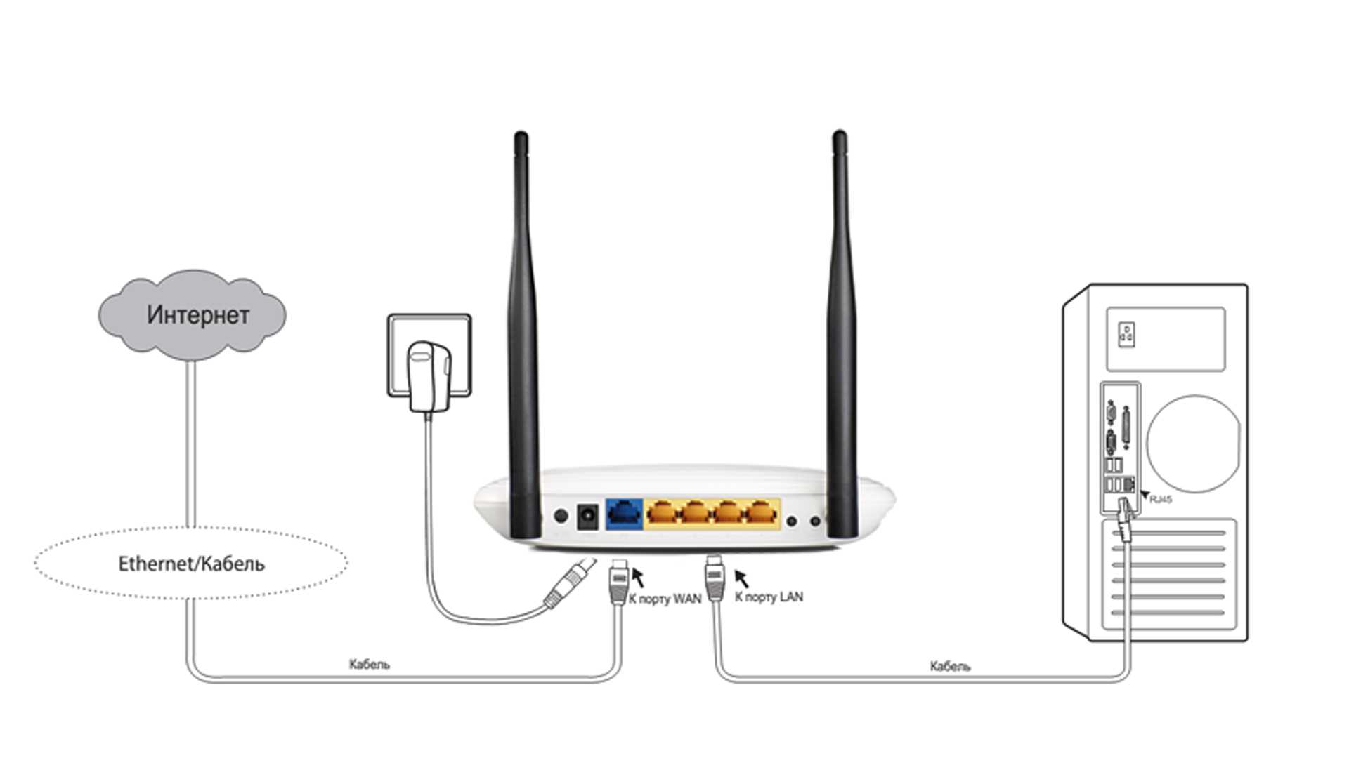
Step 6. Configure a Network Management IP Address (or Management Interface)
Next, you need to configure a network management IP address. Switches don’t come with an IP address by default, meaning that you can’t connect to it with Telnet or SSH. To solve this problem you can select a virtual LAN(VLAN) on the switch and create a virtual interface with an IP address. You can do this by entering the following command:
access-switch1(config)# interface vlan 1

access-switch1(config-if)# ip address 10.1.1.200 255.255.255.0

access-switch1(config-if)# exit

access-switch1(config)#
The new IP management address is located in VLAN1, which other computers will now use to connect.
